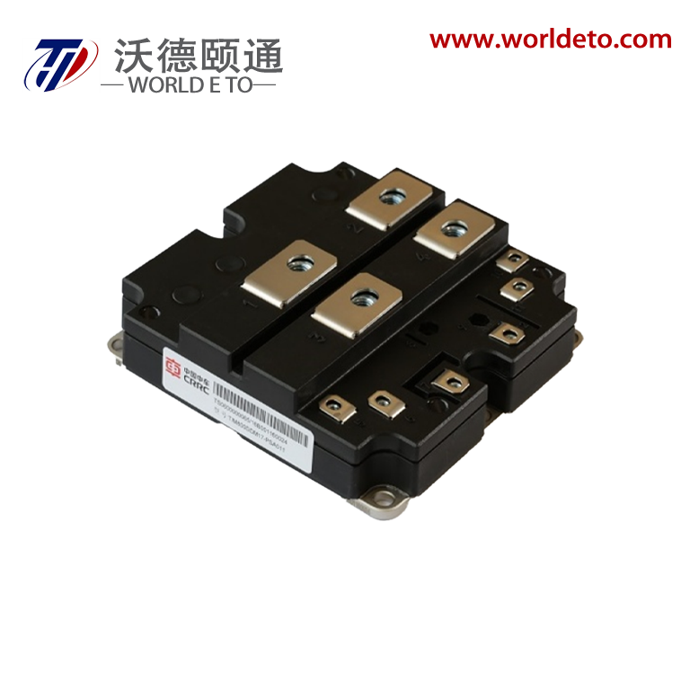
1700V 800A
Brief introduction
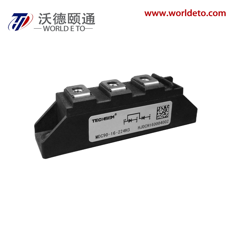
IGBT module,single switch IGBT modules produced by CRRC. 1700V 1200A.
Key Parameters
VCES |
1700 |
V |
|
VCE(sat) |
(typ) |
2.30 |
V |
IC |
(max) |
800 |
A |
IC(RM) |
(max) |
1600 |
A |
Typical Applications
Features
Absolute Maximum Rating
(Symbol) |
(Parameter) |
(Test Conditions) |
(value) |
(Unit) |
VCES |
Collector-emitter voltage |
V GE = 0V, TC= 25 。C |
1700 |
V |
V GES |
Gate-emitter voltage |
TC= 25 。C |
± 20 |
V |
I C |
Collector-emitter current |
TC = 80 。C |
800 |
A |
I C(PK) |
Peak collector current |
t P=1ms |
1600 |
A |
P max |
Max. transistor power dissipation |
Tvj = 150。C, TC = 25 。C |
6.94 |
kW |
I 2t |
Diode I 2t |
VR =0V, t P = 10ms, Tvj = 125 。C |
120 |
kA2s |
|
Visol |
Isolation voltage – per module |
( Commoned terminals to base plate), AC RMS,1 min, 50Hz,TC= 25 。C |
4000 |
V |
Q PD |
Partial discharge – per module |
IEC1287. V 1 = 1800V, V2 = 1300V, 50Hz RMS, TC= 25 。C |
10 |
pC |
Electrical Characristics
(Symbol) |
(Parameter) |
(Test Conditions) |
(Min) |
(Typ) |
(Max) |
(Unit) |
|
|
I CES |
Collector cut-off current |
V GE = 0V,VCE = VCES |
|
|
1 |
mA |
|
V GE = 0V, VCE = VCES , TC=125 ° C |
|
|
25 |
mA |
|||
I GES |
Gate leakage current |
V GE = ±20V, VCE = 0V |
|
|
4 |
μA |
|
V GE (TH) |
Gate threshold voltage |
I C = 40mA, V GE = VCE |
5.00 |
5.70 |
6.50 |
V |
|
|
VCE (sat)(*1) |
Collector-emitter saturation voltage |
V GE =15V, I C = 800A |
|
2.30 |
2.60 |
V |
|
V GE =15V, I C = 800A,Tvj = 125 ° C |
|
2.80 |
3.10 |
V |
|||
I F |
Diode forward current |
直流 DC |
|
|
800 |
A |
|
I FRM |
Diode maximum forward current |
t P = 1ms |
|
|
1600 |
A |
|
|
VF(*1) |
Diode forward voltage |
I F = 800A |
|
1.70 |
2.00 |
V |
|
I F = 800A, Tvj = 125 ° C |
|
1.80 |
2.10 |
V |
|||
C ies |
Input capacitance |
VCE = 25V, V GE = 0V, f = 1MHz |
|
60 |
|
nF |
|
Q g |
Gate charge |
±15V |
|
9 |
|
μC |
|
C res |
Reverse transfer capacitance |
VCE = 25V, V GE = 0V, f = 1MHz |
|
- |
|
nF |
|
L M |
Module inductance |
|
|
20 |
|
nH |
|
R INT |
Internal transistor resistance |
|
|
270 |
|
μΩ |
|
|
I SC |
Short circuit current, ISC |
Tvj = 125° C, VCC = 1000V, V GE ≤15V, tp ≤10μs, VCE(max) = VCES – L (*2)×di/dt, IEC 6074-9 |
|
3700 |
|
A |
|
td(off) |
Turn-off delay time |
I C =800A VCE =900V L ~ 100nH V GE = ±15V RG(ON) = 2.2Ω RG(OFF)= 2.2Ω |
|
890 |
|
ns |
|
t f |
Fall time |
|
220 |
|
ns |
||
E OFF |
Turn-off energy loss |
|
220 |
|
mJ |
||
td(on) |
Turn-on delay time |
|
320 |
|
ns |
||
t r |
Rise time |
|
190 |
|
ns |
||
EON |
Turn-on energy loss |
|
160 |
|
mJ |
||
Q rr |
Diode reverse recovery charge |
I F = 800A VCE = 900V diF/dt =4000A/us |
|
260 |
|
μC |
|
I rr |
Diode reverse recovery current |
|
510 |
|
A |
||
E rec |
Diode reverse recovery energy |
|
180 |
|
mJ |
||
td(off) |
Turn-off delay time |
I C =800A VCE =900V L ~ 100nH V GE = ±15V RG(ON) = 2.2Ω RG(OFF)= 2.2Ω |
|
980 |
|
ns |
|
t f |
Fall time |
|
280 |
|
ns |
||
E OFF |
Turn-off energy loss |
|
290 |
|
mJ |
||
td(on) |
Turn-on delay time |
|
400 |
|
ns |
||
t r |
Rise time |
|
250 |
|
ns |
||
EON |
Turn-on energy loss |
|
230 |
|
mJ |
||
Q rr |
Diode reverse recovery charge |
I F = 800A VCE = 900V diF/dt =4000A/us |
|
420 |
|
μC |
|
I rr |
Diode reverse recovery current |
|
580 |
|
A |
||
E rec |
Diode reverse recovery energy |
|
280 |
|
mJ |
||
Our professional sales team are waiting for your consultation.
You can follow their product list and ask any questions you care about.